1. Introduction 6j1715
The elbow and forearm are frequently affected by traumas that can cause fractures (Pererira Jnior, Gonalves, 2006). Those traumas can lead to sequels such as: the modification of the load angle (varus or valgus), rigidity of movement, especially after prolonged immobility or more complex deformities.
The t immobilization used after injuries, causes muscle disorders such as a decrease in the muscle fiber area with a reduction in strength capacity and alteration in the percentage of predominant fibers; increasing the number of fast twitch fibers. This causes functional implications regarding the mechanical properties of the muscle and the ability to resist fatigue (Karolczak, 2006).
Saringer, Culhane (1999, 2005) and Culhane et. al. (2001, 2006) claim in recent years, the importance of rehabilitation and treatment of t injuries and adjacent soft tissues by continuous ive motion applied to the ts by the continuous ive motion (M). This modality is controlled and does not require any muscle coordination, which maximizes recovery and because it does not lead to muscle fatigue, it allows maintaining movement for longer. According to Beny, Oster (2004) the advances in auxiliary technology, motor control and adjustable equipment have promoted ive motion with orthoses, which used to be performed only by professionals.
In trying to use innovation with current M equipment, the general objective of this study is to develop a M equipment prototype, controlled by a computer with the purpose of enabling pre-programming of various movement sequences, allowing for the automatic execution of the ive motion of elbow and forearm. The specific objectives are to perform the conceptual design of the mechanical parts of the equipment and to produce a prototype utilizing computerized numerical control (CNC) technology to control the machine.
2. Methods 1x6k6f
Recommendations from the project methodology were used in the planning phases and in the conceptual design (Back, 2008) for the development of the M computerized Equipment Project for the elbow and forearm.
Biographical research was carried out in databases and patents and ten pieces of M equipment for elbow and/or forearms were identified. Six out of the 10 pieces of equipment enable elbow flexion/extension; two of them provide pronation/supination of the forearm and only two performed elbow flexion/extension and/or pronation/supination of the forearm in the same equipment. All of them alledge having the possibility of controlling the speed and ROM. Seven are programmable; however, availability for pre-programming iss not reported. Regarding the specification of the type of motors, five of them are electrical (three from direct current, DC), and the others are not specified.
Also, five commercial types of elbow and forearm M equipment available on the market were analyzed. Kinetec 6080 Elbow M Machine, E3 Elbow M Device, Kinex KE2 Elbow M, JACE Elbow M eArtromot E2 Elbow M. All of them enable elbow flexion/extension and forearm pronation/supination: ROM varies from one equipment to the other. The extension limit is between -15% and 0%, the limit of flexion is between 130 and 160, pronation limit is between -80 and 90 and supination between 80 e 90. All of them have direct current (DC) motors and are micro processed, with the possibility of ROM, time and speed pre-programming.
In addition to bibliographical and market research, surveys were carried out with 53 physical therapists individually from the Orthopedics and Traumatology field, which are the main areas for the application of M equipment and also with four elbow and forearm surgeons from the cities of Santa Maria and Porto Alegre. They answered four open questions with the aim of finding out their opinion of the importance of the elbow M equipment for the physical therapist and for elbow pathology treatment and knowing if the interviewees have the equipment or if they would like to have it in their clinic/laboratory. In addition, the clinical applications of M equipment were discussed and the clients’ requirements for help in posterior project construction (Table 1) were identified.
Interview data |
Physical Therapist |
Physicians |
|
Total number of interviewees |
53 |
4 |
|
Do not know any elbow and forearm M equipment |
28 |
0 |
|
Know some elbow and forearm M equipment |
25 |
4 |
|
Importance |
Important to Physical Therapist and patient recovery. |
24 |
4 |
Not important to Physical Therapist and patient recovery |
1 |
0 |
|
Do not have opinion because they do not know the equipment. |
28 |
0 |
|
Do they have or would have the elbow and forearm M equipment? |
Do not have |
53 |
4 |
They would like to buy it |
44 |
4 |
|
They would not like to have |
4 |
0 |
|
Do not have an opinion |
5 |
0 |
|
Requirements mentioned by the interviewees. |
Reliability, flexibility, safety, easy to operate and maintain, compact and affordable, |
Variable angular positioning, variable speed |
|
Chart 1 – Physical Therapist and Physician Research.
Based on scientific publications and patents, on the technological advances of interpretation as well as on individual interviews carried out among physicians and specialists in elbow and forearm, the s’/clients’ requirements were listed regarding Elbow and Forearm computerized M prototypes and later these were implemented into the project technical requirements (Chart 2).
According to the technical requirements of the project, the function/operation and the parameters of the research problems were identified. Alternative principles were investigated for each function and/or parameter by using recommended morphological matrix methods (Back, 2008). After that, the options were combined and compared in order to find the most appropriate solution to the design of the proposed equipment.
/client requirements |
Technical requirements of the project |
Operation practicality |
Ease in programming, pre-programming availability and friendly interface. |
Reliability |
Possibility of reproducing programmed operations |
Flexibility |
Pre-programs adaptable to the aims of the treatment. s are adaptable to normal anthropometrics measures for the upper limbs. |
Safety |
Quick access to program cancellation |
Compactness |
Simplicity of the transmission and drive components. |
Affordable |
Application of commercial components. |
Chart 2 – The implementation of /client requirements for computerized M project technical requirements.
Chart 3 presents three options. The third one was chosen because it is the most appropriate for the research objectives.
Functions and/or Parameters of the problem |
Alternative principles for each operation or parameter |
||
Option 1 |
Option 2 |
Option 3 |
|
To drive the equipment |
Servo motor |
Alternating Current (AC) motor with frequency inverter |
Stepper motor |
To move the elbow and/or forearm |
Independent control |
Independent control |
Independent control |
To facilitate the angle, time, and speed adjustments. |
The Physical Therapist offers data regarding time and ROM so that the software may determine the speed. |
The Physical Therapist provides the speed directly. |
The Physical Therapist offers data regarding time and ROM so that the software may determine the speed. |
To stop the movement |
Sensor |
Switch |
Switch |
To record ROM, speed and time |
Graph Record |
Descriptive Record |
Graph Record |
To create the CNC program |
Development of a single program |
CAD/CAM System |
Development of a software generator for the CNC program |
Software control |
Development of a control program |
Commercial Software |
|
Chart 3 – Alternative Design.
3. Results v3rz
Detailed Design 3u6v29
The detailed design (Figure 1) shows an innovative product, which enables the subject, through programming, to perform sequences of precise movements of the elbow and forearm at pre-determined angles. The ive motion, performed by the equipment, is for the extension/flexion of the elbow from 0 to 160, and forearm pronation/supination from -90 to 90.
The equipment consists of stepper motors controlled by software, which receives the data generated by other software, interprets them and sends the information through drivers to the motors that drive the axles through synchronized and independent movements. The computerized M can be applied to both upper limbs, enabling computerized control of time and for the ROM to calculate automatically the speed from the data provided by the physical therapist.
The equipment structure includes an adjustable vertical rod (Figure 1), fixed at the lower end to a base in a cross shape (Figure 1-2) with four wheels (Figure 1-3). At the upper part of this rod there is an assembly attached, which is responsible for the elbow flexion/extension movements (Figure 1-4). This consists of a metal plate (Figure 1-4.1) where they are fixed by: pulleys (Figure 1 - 4.2), axles (Figure 1 - 4.3), belts (Figure 1 - 4.4), and stepper motor (Figure 1 - 4.5).
The motor is connected to the drive axles of the flexion/extension movement (Figure 1-4.3) through pulleys (Figure 1-4.2) and belt (Figure 1-4.4). The arm ing base (Figure 1-5) is connected to the rod (Figure 1-1) and has adjustable angular positioning that allows for an inclination of up to 45 in the sagittal plane of the patient's body. This base contains the arm / (Figure 1-5.1) and also an extension adjustment mechanism (Figure 1-5.2). The lateral rods from the arm ing base (Figure 1-5) fit the lateral rods of the forearm ing base (Figure 1-6). This base contains the for the forearm (Figure 1 - 6.1) and also has an extension adjustment mechanism (Figure 1 - 6.2).
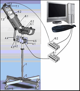

At the other end of the forearm rod (Figure 1 -6), an assembly is attached which is responsible for forearm pronation/supination (figure 1-7) composed by a plate (Figure 1-7.1), where the stepper motors (Figure 1-7.2) and the handle are fixed (Figure 1-7.3). This component is directly connected to the motor axle which can perform the movement of pronation/supinatino from -90 to 90, starting from the neutral position of the forearm. The stepper motors (Figure 1-4.5 and Figure 1-7.2) are connected to a computer (Figure 1-8) through drivers (Figure 1-9 9.1 and 9.2).
Equipment prototype 615v6w
Based on the detailed design, a prototype of the Computerized Elbow and Forearm Equipment was produced (Figure 2). It was created in the Manufacturing Process and Automation Center (NAFA) at the Technological Center of Santa Maria Federal University.
The constituents of the prototype are mostly commercial; either in parts or profiles that were adapted to the exigencies of the equipment. Measures were taken to improve the quality of the prototype; the commercial parts of the prototype: ing base, adjustable vertical aluminum rod, clamps, pulleys and belts; were all built from commercial aluminium plates. The lateral rods and the arm and forearm ing base; extension adjustment mechanism for the forearm; the plate where the pronation/supination motor is secured; the handle structure; the securing plate for the elements responsible for flexion/extension are all made of steel. The material was chosen taking into the weight and the possibility for sterilization of the parts that could be in with patient’s body.
Two stepper motors were used, considering versatility and ease for their digital control (Araujo, 2005). Furthermore, the torques of both are sufficient for the axles’ movement of pronation/ supination, as well as flexion / extension axis.

Figure 2 – Computerized M prototype.
The drive system of the M equipment consists of the prototype that is connected to a microcomputer by means of drivers, via parallel doors. The control is made by the commercial software Mach3 (Artsoft, 2008) configured according to the motors utilized and the actual requirement of the equipment. This program reads and interprets the data provided by the automatic software generation of the CNC program created for this equipment.
This software, developed in Borland/Delphi 2009 programming language, creates a text file, which contains the movement sequence created by the physical therapist in G code – read through computerized numerical control. This file needs to be saved to be read either by text-editing programs or by the control program.
In addition, the software calculates the speed of the movement based on the ROM and time provided by the , and it can also convert the angle into pulses so that this program can be used in specific programs of CNC control.
Software generator for the CNC program 14454t
The interface of the program (Figure 3) has a sheet in which the inserts the angles (degrees) and the time (seconds) to create a sequence of movements which will be performed by the equipment for movements of flexion/extension as well as pronation/supination. In the lower part of the interface there are three boxes where three constants are configured by the programmer, according to the resolution of the control program. They do not need to be modified by the any longer. The two graphs, present in the interface, show the sequence of the movements: angles (degrees) in the axle of the coordinates, by function of time (seconds) in the abscissa axis, according to data provided by the Physical Therapist in Sheet 1.

Figure 3 – Program Layout.
Example of movement sequence programming 6h5cv
Figure 3 demonstrates the alternative of performing only the elbow flexion/extension. The Physical Therapist fills in the first and second columns of Sheet 1, all the times and angles, to create a sequence of movements. The first graph shows the sequence being created. When the sequence is completed, it should be saved and then it starts to execute. The first and the second columns from Sheet 1 and the second graph are marked as zero because they are related to the forearm pronation/supination movements and there is no sequence of movement programmed for this axle.
The example in Figure 3 demonstrates, on the first line of Sheet 1, that the equipment is positioned at 40 of elbow flexion for 10 seconds. This movement occurs at a speed of 4/sec, but is hidden in the interface; however, it is calculated by the software and displayed in the text file created by the control program. On the second line, for the following 30 seconds, the equipment is going upto 70 of flexion, from the initial position of 40 at a speed of approximately 2.34/sec. On the third line, the arm extends to 70, returning to 40 of flexion, in 30 seconds at a speed of, approximately, 2.34/sec; the same as the previous line because the time and ROM provided are the same. The fourth, sixth and eighth lines have the same controls as the second one; therefore, the speed is also the same. The fifth, seventh and ninth lines are the same as the third one, as well as the speeds. On the tenth line, the elbow extends to 40 in ten seconds at 4/sec, then returns to the initial position. The initial position can be at any angle, it is necessary to place it on the first line in order for the equipment to be positioned.
This first sequence of movements shown is an oscillation degree II (Kisner, 2005) in which rhythmic movements of large amplitude are performed without reaching the flexion amplitude limit. This same example can be used for the pronation/supination movements without reaching the ROM limit of these movements. Also, movements solely for the pronation/supintion axis can be programmed as well as a sequence of movements equal or different for the two axles simultaneously. They occur at the same period of time, however, each sequence in its own axle.